


Note : Bearings can be standard configuration or uniquely designed by the project engineer or architect. The plan should not be altered without the approval of the designer.
As construction engineering advances, more frequently Slide Bearings are being designed with bonded rubber layers to allow for rotation and/or vibration isolation. There is a standard configuration for these bearings and some basics should be understood.
In any Slide Bearing assembly, the upper element is always larger than the lower element. Fig. 1. This provides two important advantages:
Fig. 1 Standard FC-1010-CS Slide Bearing. Gold element shown is Fluorogold®. Also available in virgin Teflon® (white).
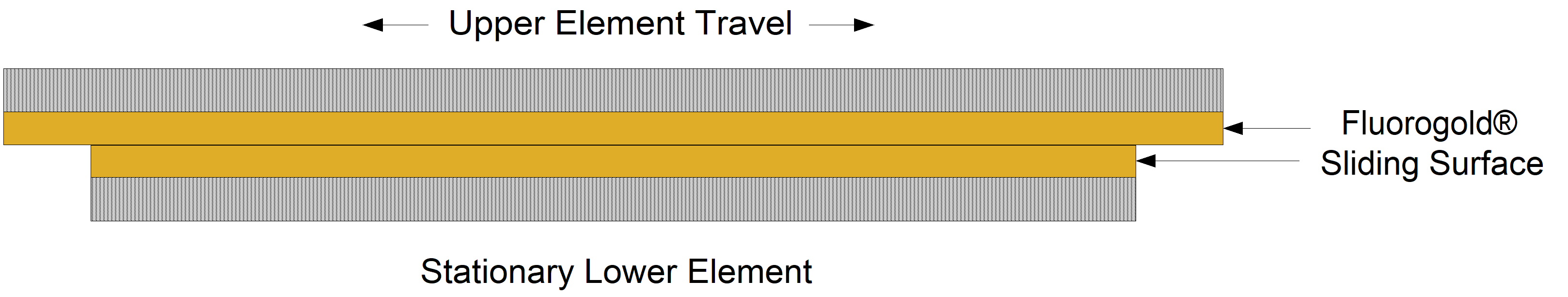
- The load on the lower element is consistent.
- The lower element is never exposed and therefore cannot collect any abrasive debris on the surface. Picture a slide bearing supporting a pipeline. It is usually exposed to the elements and in an area where abrasive contaminants are everywhere. By keeping the lower element fully covered it prohibits these abrasive particles from embedding themselves in the Teflon® or Fluorogold® surface.
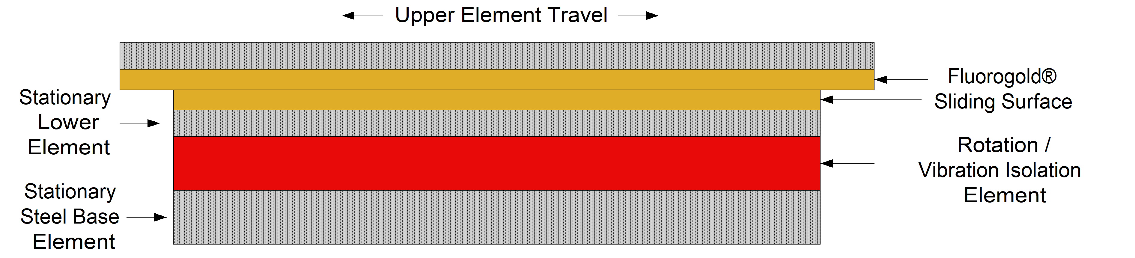
The addition of a flexible layer allows for rotation and vibration isolation. Fig. 2. This layer can be any one of the neoprene derivatives or one of the flexible alternatives such as Viblon® or Sylodyn®. In this case the flexible element should be located as the next layer above the steel base element.
Fig. 2 The sliding element (gold) is located above the rotation element (red).
All bearings are based on PSI calculations. Typical situations allow for the lower element to remain stationary while the upper element expresses the horizontal movement the bearing is designed to allow.
Example: A slide bearing has a lower element sized 10” x 10” and an upper of 12” x 10” to allow for travel. The upper element is irrelevant for psi calculation. The lower element of 10” x 10” is 100 sq. in. If the load is 90,000 lbs., the psi is 900 lbs. This is well withing the range of Teflon® or Fluorogold®
Fig. 3 illustrates why locating the flexible layer below the sliding layer is important. As the upper element travels the lower element remains 100% covered and the load remains consistent at 900 psi across the surface.
Fig. 3 The Upper member has expanded or contracted and the load has shifted. However, it remains a consistent 900 psi on the lower element.
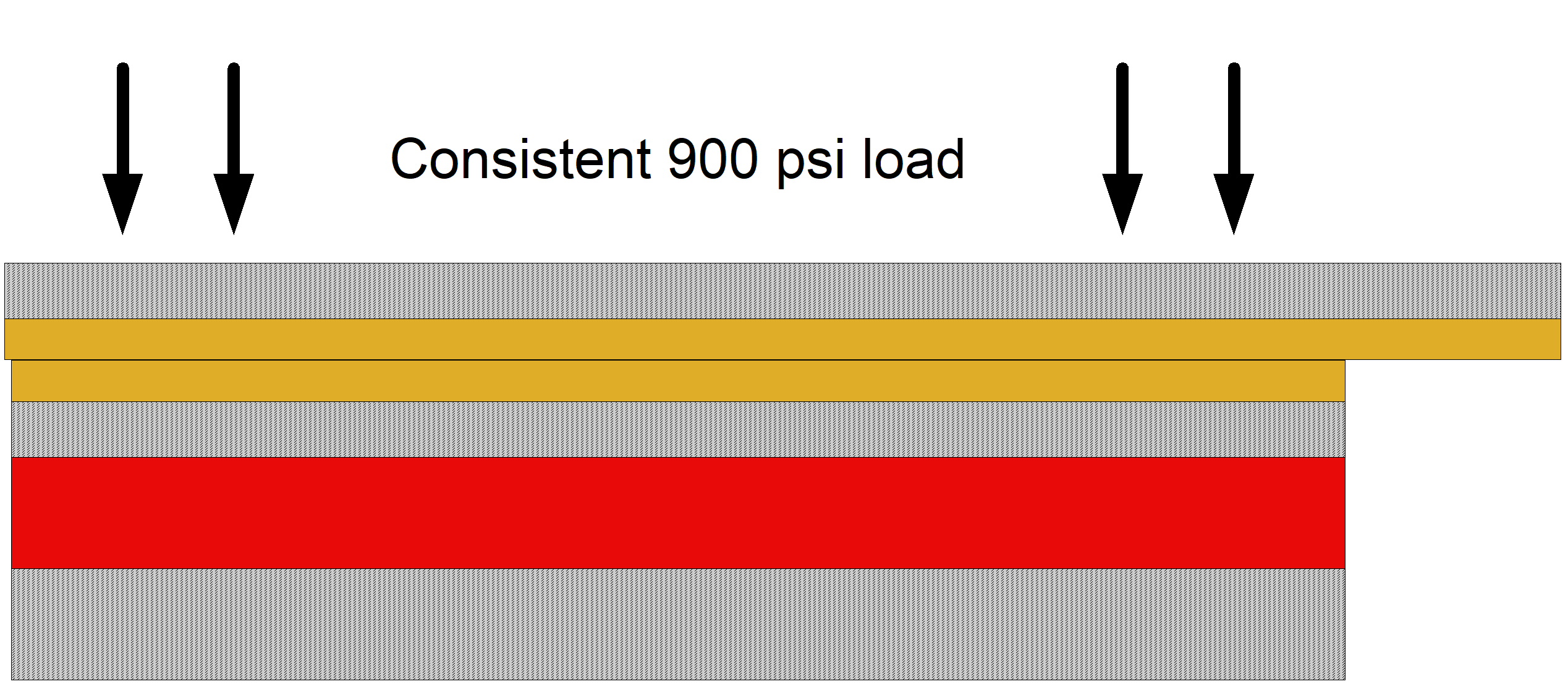
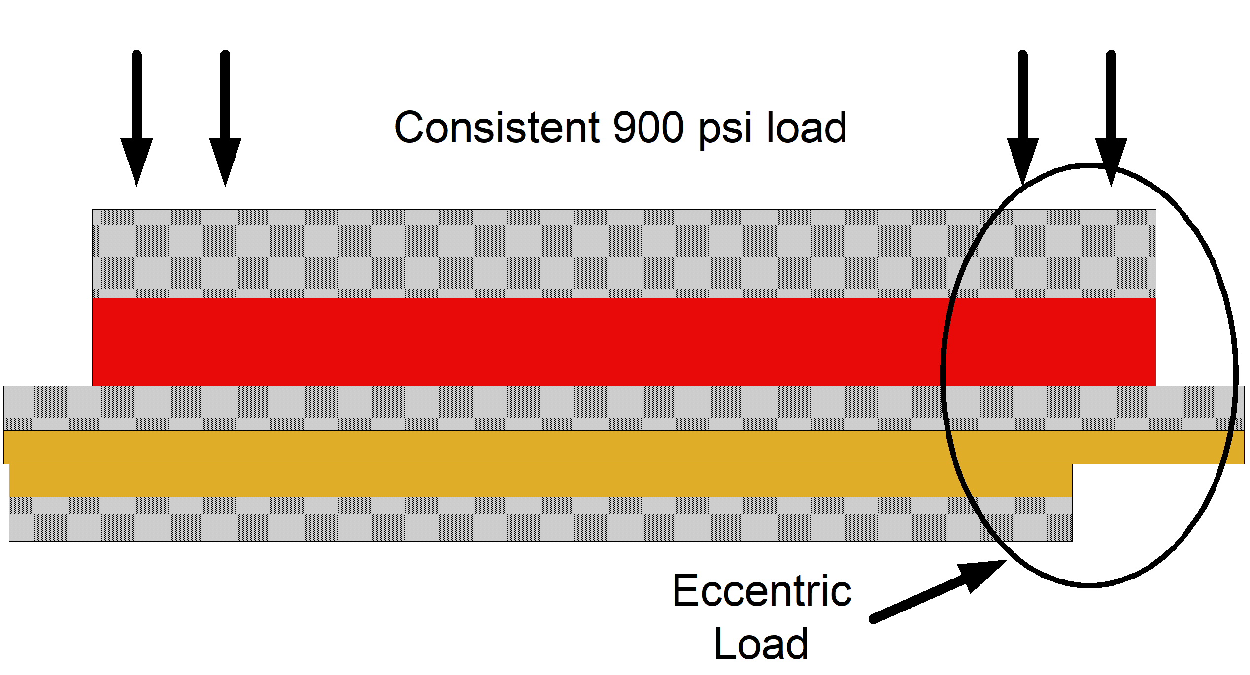
Fig. 4 shows the flexible layer located above the upper sliding element. As travel occurs the rotation would cause the load to be transmitted unevenly. This creates a situation known as a “Load Line” with more of the pressure focusing on the compressed edge. By focusing the pressure on a limited surface area, the psi has increased and could easily exceed the 2,000 psi limit provided by Teflon® or Fluorogold®.
Fig. 4 While load is still 900 psi above, it is transmitted unevenly to the lower member. Note right side of bearing assembly.
With any of these situations, if any questions exist feel free to contact us with your concerns. We will be glad to work with you and/or your engineer or architect to design an effective solution.